WebIO supports several X10 powerline transceivers
Supported X10 powerline transceivers include:
- The
Smart Home Powerlinc serial interface transceiver (with RJ12 6pin modular
connector) in TW523 mode. With this transceiver the WebIO also receives
power from the Powerlinc, so no extra power supply is needed.
- The
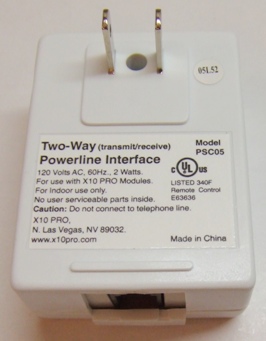
X10 Pro PSC05 (TW523) transceiver. An additional 9-12 Volt DC, center pin
positive, power supply is required to power the WebIO. Along with a
jumper changed within the WebIO.
- The
PL513/PCS04 transmitter. With the PL513 WebIO can transmit X10 signals
but not receive message replies from 2-way X10 modules. In addition a
separate power supply is required for WebIO.
- The
XM10 transceiver for 230VAC 50Hz power in UK countries. In addition a separate
power supply is required for WebIO.
|
|
|
|
| WebIO Transceiver Power Jumper (J6) |
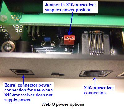
WebIO Power Jumper (J6)
WebIO can be supplied with power when using the Smart Home Powerlinc II X10 transceiver with WebIO,
such that an additional power supply is not required to power WebIO via WebIO's power barrel connector.
To enable power to WebIO from the Powerlinc, WebIO jumper J6 must be positioned, such that the two of three J6 pins
closest to the X10 modular connector are shorted. (see picture of red jumper in Powerlinc powered position)
To access the WebIO power jumper, the top cover must be removed.
Be sure to disconnect WebIO from power and/or X10 transceiver before openening up WebIO.
A long nose pliers is ideal for moving WebIO jumper. The jumper maybe a different color then pictured.
You should discharge any static electric charge you may have before working with WebIO.
|
|
Inside view of WebIO v2 power jumper (J6)
|
|
| Powerlinc X10 Transceiver |
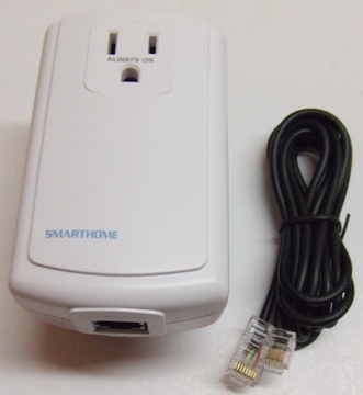
Powerlinc powerline X10 Transceiver
The Smart Home Powerlinc II X10 transceiver (pictured to the right) provides the following features when used with WebIO:
Transmits and receives X10 codes
Provides WebIO with power and X10 in one cable. (no additional powersupply required)
Provides front feed through outlet for other AC devices
Requires included cable for connection to WebIO
|
|
|
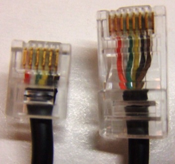
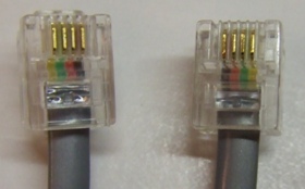
Powerlinc II cable used with WebIO:
6P6C modular plug (RJ12) connects to WebIO
8P8C modular plug (RJ45) connects to Powerlinc
|
|
| PSC05/TW523 X10 Transceiver |
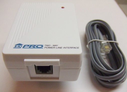
PSC05/TW523 X10 Transceiver
The PSC05 powerline X-10 transceiver (pictured to the right) provides the following features when used with WebIO:
Transmits and receives X10 codes
Uses standard RJ11 "phone cable" for connection to WebIO
LED indicator "winks" when WebIO sends an X10 code
LED indicator "winks" when an X10 code is detected on the powerline
DOES NOT provide WebIO with power. (9-12VDC center pin positive power supply required to power WebIO via power barrel connector)
|
|
|
|
|
PSC05 cable used with WebIO:
("phone cable" 6P4C modular plugs (RJ12)
|
|
| PSC04 X10 Transmitter |
PSC04 X10 Transmitter
The PSC04 X10 transmitter can be connected to WebIO, but requires a cable change.
The PSC04 allows WebIO to transmit X10 messages onto the power line,
where as the PSC05 X10 Transceiver also allows WebIO to receive X10 messages for specific WebIO functions.
The PSC04 looks identical to the PSC05.
Above: PSC04 pinout
|
|
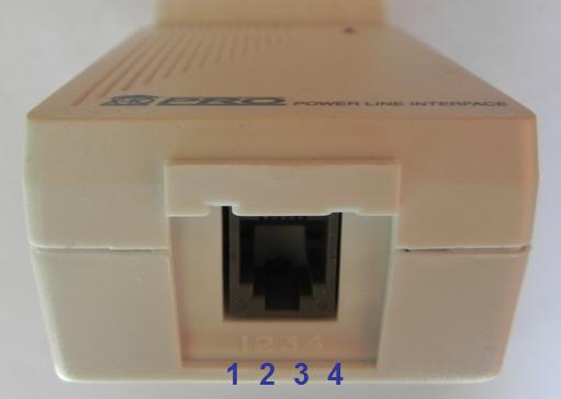
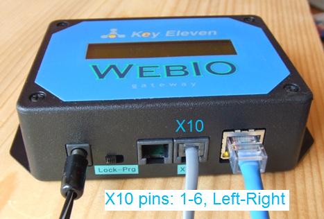 Image above: WebIO X10 pins 1-6, left to right.
WebIO 6 pin Module connector pin out:
1. 9-12VDC (optional) from X10 Transceiver
2. X10 data transmit
3. X10 data receive (PSC05 only)
4. WebIO Ground
5. Zero Crossing Detect
6. WebIO Ground
|
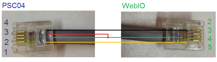
Pin numbers on PSC04 end of cable (Blue colored numbers in image above) correspond to pin numbers labeled on the PSC04 Unit.
Pin 2 & 3 of PSC04 end of cable must be connected together. These are Ground connections.
PSC04 pin 1 is X10 Zero Crossing, pin 4 is X10 signal to transmit.
The WebIO end of cable, Pin #4 (Green color in this pictured example) supplies Ground to Pin #2 & #3 of PSC04.
WebIO Pin #3 (Red color in this pictured example) must not be connected to the PSC04.
(WebIO Pin #3 is the X10 input pin, used when connected to a PSC05 2-way X10 transceiver).
Pin #5 of WebIO end of cable (Yellow in picture) is X10 AC power zero crossing signal.
|
|
|
|
| Firecracker Wireless X10 Transmitter |
Firecracker Wireless X10 Transmitter
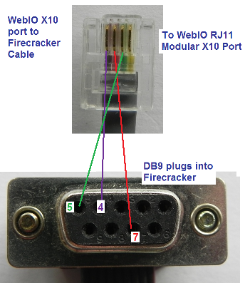
WebIO v3.3 and greater also works with the very low cost Wireless X10 Firecracker transmitter model CM17a.
This requires a special cable (RJ12 to DB9 cable) that allows plugging in an external Firecracker to the WebIO X10 interface connector (RJ12).
The Firecracker then requires an X10 wireless receiver such as the TM751 or RR501 to transmit the Firecracker Wireless signals onto the powerline.
The Firecracker is a transmit only device. This does not allow WebIO to get a status response from 2-way X10 devices such that WebIO cannot query X10 devices.
The Firecracker as a WebIO X10 interface can provide a very low cost form of X10 control and be useful to work around problems with a WebIO installation having direct access to AC powerlines.
Important: The X10 wireless receiver, powerline transmitter TM751 or model RR501 only transmit X10 commands
onto the powerline that have a House Code equal to the House Code set on it's House Code dial.
For WebIO to send X10 messages to multiple house codes, you will need one TM751/RR501 per house code (each set to a specific house code).
|
|
|
|
|
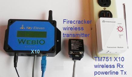
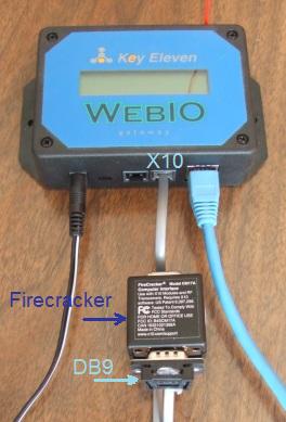
Image above: WebIO connected to Firecracker X10 wireless transmitter.
Also TM751 X10 wireless receiver, which relays the wireless X10 messages onto the AC power line.
|
|
|
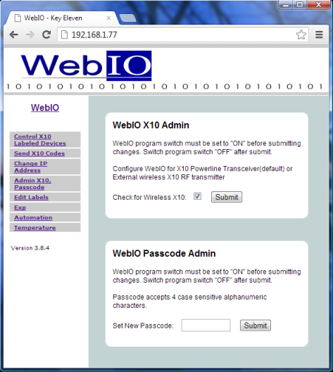
WebIO Wireless Transmitter Configuration
WebIO v3 needs to be configured to use the Firecracker wireless X10 transmitter in place of a powerline X10 Transmitter.
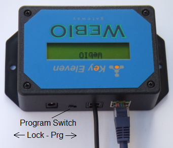
From the WebIO web interface go to menu link: "Admin X10, Passcode",
place the WebIO into "Prg" mode using the "Lock-Prg" switch and then check the "Check for Wireless X10" check box.
When finished place the "Lock-Prg" switch back into the "Lock" position.
|
|
|
|